
The G4ATA EFT antenna (pat pending!)
As briefly mentioned in the "Antenna" section of my "Current Setup" page I am severly restricted for antennas. Apart from having a very small rear garden I have issues with neighbours that are far too complicated and boring to go into here.....suffice to say that one of them believes that she is in desperate need of a tin foil hat to protect her from my cancer causing and global warming radio transmissions! The less said the better!!
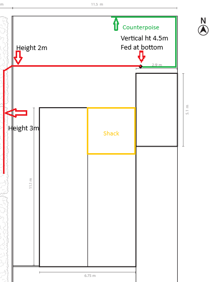
My rear garden ("yard" for our American friends!) is only
11.5m x 6.5m or 37ft x 21ft in old money. Pretty small even by UK
standards. The image below shows the layout of the antenna as of January
2026.
The vertical section is 50mm OD aluminium attached to (and insulated from) T & K
brackets. From the top of that pole and for the counterpoise I have used
4mm PVC coated Flexweave. The total length of the antenna is approximately
75ft and the counterpoise 35ft. The counterpoise is raised above ground
approximately 1ft.
At the feed point I have a homebrew 9:1 balun that is preceeded by a homebrew
bifilar wound common mode choke that is wound on 2 x 240-T31 ferrites. The
balun performs well and makes the required impedance transformation.
The CMC also performs well at power levels up to 200 watts from my FTdx101MP.
However, the CMC isn't so happy if I strike up my Acom 1010 and raise the power
levels. It generates heat and after a short while the SWR rises.
With the exception of 80m where it quite happily copes with 500 watts of CW for
hours. I suspect this is because the choke's impedance becomes resistive
at frequencies other than 3.5MHz'ish resulting in core heating. At some
point in the future I will investigate the use of a different choke for
QRO and the higher frequencies....watch this space!! There is loads of info
available on the web regarding baluns and chokes. One of my "go to" sites
is
http://www.karinya.net/g3txq/chokes/
In the meantime I restrict QRO activity to 80m.
Apart from the CMC issue the next item on my agenda for this antenna is to raise it's overall height over it's whole length to approximately 4.5m. Again, watch this space!
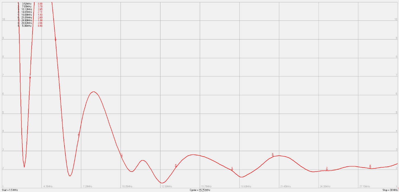
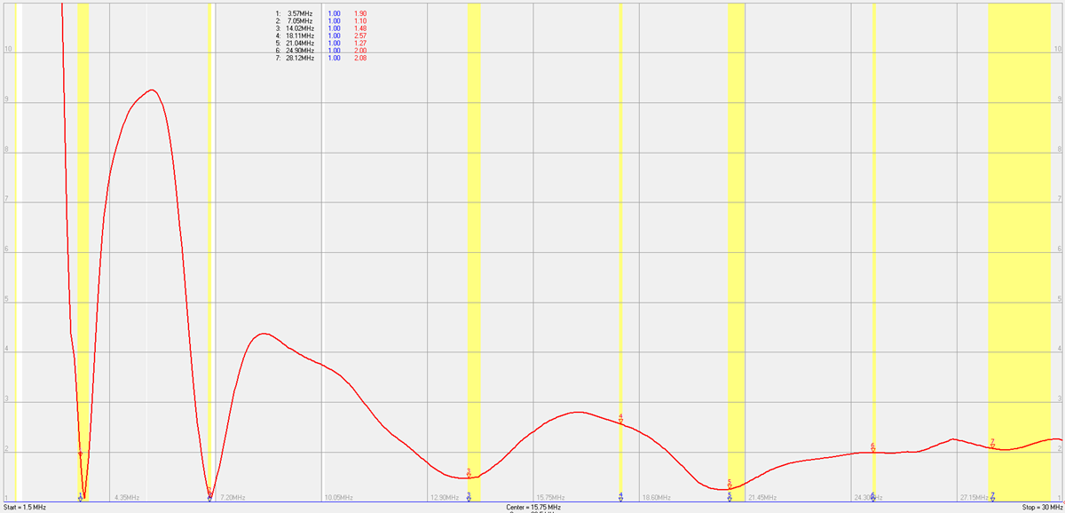
Below is a plot of the SWR of the EFT in it's current
iteration ...... the markers are set for the CW portion of the bands. This
plot was made using my FA-VA5 designed by DG5MK using the DG8SAQ Vector Network
Analyser software for the DG8SAQ VNWA ..... see
SDR-Kits - note the FA-VA5 is no longer available and has been superceeded
by the FA-VA6.
I am currently in the process of modelling the EFT in EZNEC to compare the real
world results with my best efforts of the model in the software.....watch this
space!!
Today, 10th February 2026, I had the antenna down to do
some more accurate measuring of the wire to try and get it a little higher in the
hedge at the side of my property. At the same time I tried adjusting the
length of the wire longer and shorter up to a maximum of around 10ft. The
wire actually measures 67ft which actually works out pretty well if you take
into account a velocity factor of 95% for insulated wire. My "target
length" was 72ft that is a popular length for this type of antenna. The
vertical section is a 50mm ally pole so I'm sure there would be some VF to take
into account there.
I tried lengthening and shortening the antenna with very mixed results.
Some bands improved at the expense of others for each attempt. It was
similar for adjustments to the counterpoise too so I think I've been pretty
lucky to hit a sweet spot. I'm sure that there will be those that have
better results with different lengths but due to the constraints of my plot and
proximity to the house (bungalow actually) etc I feel that I'm getting the best
out of this particular configuration.
I did manage to get the low section a little higher into the hedge that has
resulted is slightly lower SWR on 80m & 40m and marginal difference on the other
bands.
Hopefully I will be able to get the horizontal section of the antenna raised some time in the next few weeks......fingers crossed for further improvements!
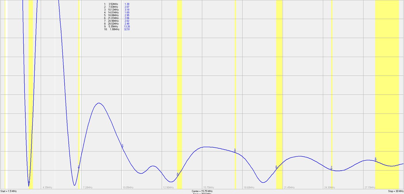
EFT MkII - 02/03/2026
I managed to increase the height of the horizontal sections of the antenna.
The counterpoise remains unchanged but from the top of the vertical section it
now rises to about 5m supported by a fibreglass pole, then turns 90 degrees for
the rest of it's length it slopes down to approximately 3m. Below is the
plot of it's SWR in it's current form
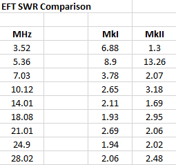
Below is the comparison of SWR values between the original and MkII versions.
Remember they both use exactly the same counterpoise and wire......the only
thing that changed was the height of the horizontal section. As you can
see, there is a marked improvement on 80m & 40m. The only band that
suffered was 60m but I can live with that! My HC-2000 ATU still manages a
match to keep the rig happy! The HC-2000 even manages to make a match on
top band in spite of the SWR being over 30:1!!!
All of my contacts are automatically uploaded to Club Log
and the table below shows a summary of DXCC and bands that I have worked in 2026
since 1st February using this antenna.....all CW of course. The vast
majority of these contacts have been made using 200 watts or less.

May 2026
Another small update to the EFT. I have increased the height of the
horizontal sections my another metre. I have not made any change to the
overall length of the wire or counterpoise. The antenna is quite
sensitive to any changes as you can see if you compare the plot of SWR below
with previous versions further up the page......quite a difference considering
how small the change was. I can now use it without an atu in the CW
section of 40m. However, the SWR low point on 80m has now moved up into
the SSB part of the band.
I knew from the start that any multi band antenna comes with compromises and
have just confirmed that any changes that I make may improve things on one or
two bands but at the expense of the others.
Another thing that I have noticed is that I do seem to be very much in the hands
of the "propagation gods" (aren't we all though!) as far as any reasonable DX is
concerned. If the conditions are favourable to me I have managed to work
some nice DX and even managed my way through a few busy pileups.
Below is an update on my DXCC stats as of 21/05/2026

This page last updated 21/05/2026 (dd/mm/yyyy).